Generation 2014-2017
 Our robots are outfitted with specially developed circuits and PCB. The development is done using the toolchain EAGLE by Cadsoft, which is a professional software bundle for PCB development. Furthermore, we also assemble all boards ourselves.
The main improvement of this generation is an enhanced modularization concept allowing us to replace boards individually: Now, our bot consists of ten different boards, each developed and optimized for a specific task. The following sections will give a brief overview about the most important board types.
Power Distribution Board
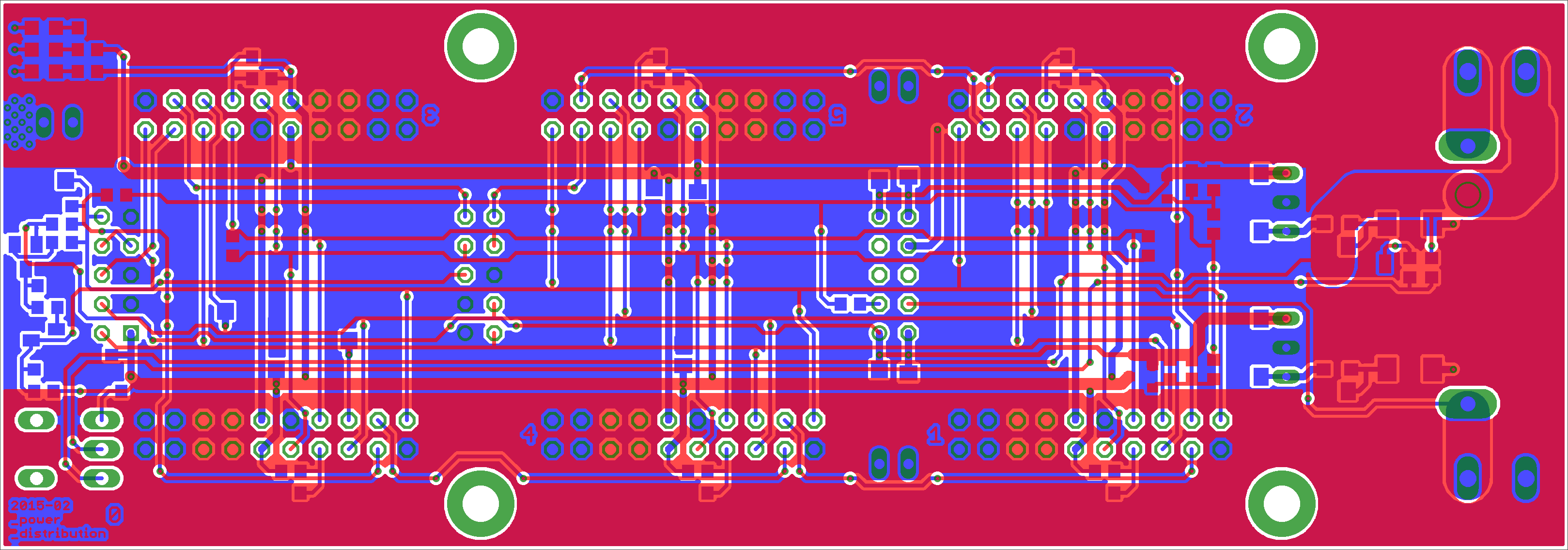 The power distribution board is the center of the robot. As suggested by its name, this board takes care of the generation and distribution of all the supply voltages. More precisely, it has connectors for the lithium polymer accumulators, generates the 3V3 and 5V0 voltage levels and distributes these to the separate module boards as well as to the main board. To prevent damage in case of malfunctions the board is equipped with security measures, like fuses.
Besides this, the power distribution board also provides six module connectors with a standardized connection interface to allow for the independent development of arbitrary boards, which can then be changed, added, or improved individually, without having to change all the other components. This feature is a major improvement over the last generation, as it greatly simplifies maintenance while offering the ability to improve and adapt the board types individually.
Before its introduction, even minor changes to small parts of the circuitry forced us to replace the whole main board (which contained both the current main board and some parts of the motor boards). Failed components usually resulted in replacing the whole board as diagnosing failures was pretty difficult. With the modularization concept we are now able to test each board separately thus simplifying fault diagnosis. That’s why we greatly encourage other teams to develop a modularized electronics design.
Main Board
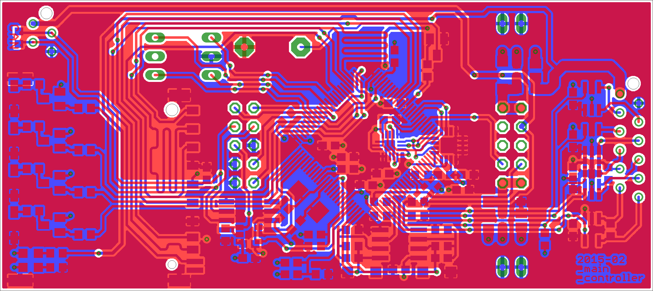 If we were to refer to the power distribution board as the body of the robot, the main board would be its heart and brain. This board does all the managing and organizing, which means that it controls the CAN bus and communicates with the central PC via our NRF boards (see later).
In the current design the main board no longer contains the motor boards but only the important and unique components, like the gyroscope, the accelerometer and the central processing unit. This is complemented by some debugging tools, e.g. a SD card connector, which greatly simplifies debugging our motion control.
Motor Controller
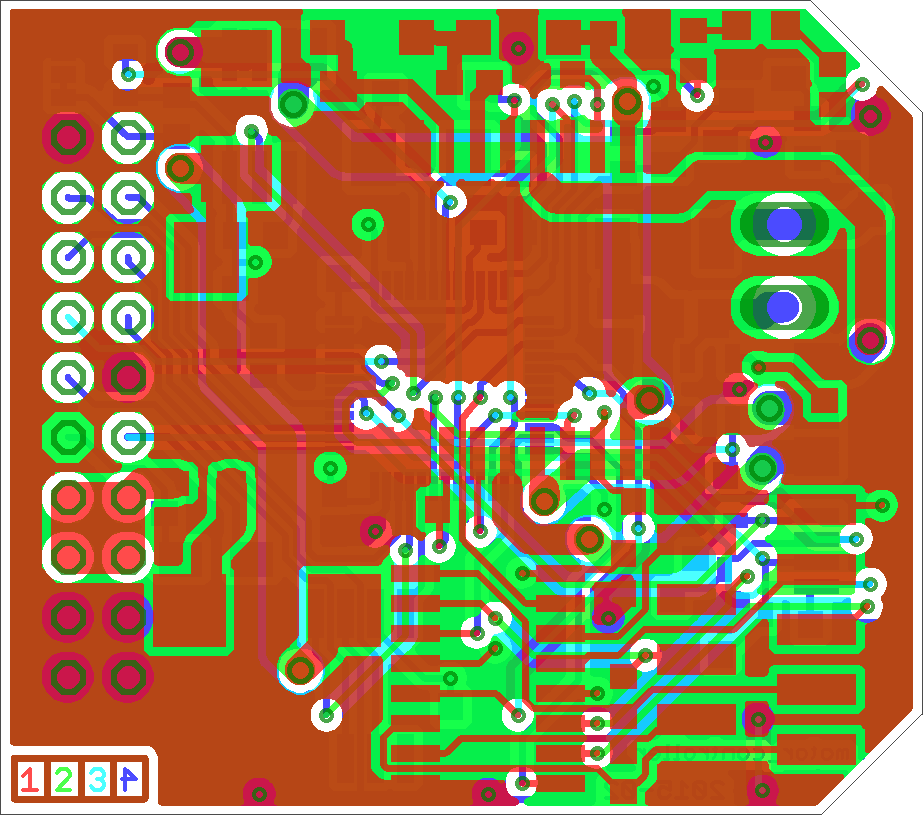 One key difference between the old and new generation is that each motor is controlled by its own module board, containing all the relevant parts. The board powers the motor and measures both its speed and current consumption. By doing that, the motion control – running on the micro controller soldered onto the motor board – can precisely control the driving dynamic of the robot.
Flyback Controller
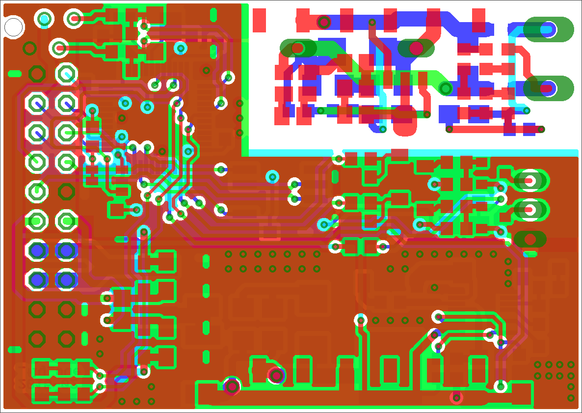 Shooting the ball relies on the electromagnetic principle. We accelerate a magnetizable kicker with a current-carrying coil. Please refer to the mechanics section for further information about the kicking system. To maximize the shoot power, we need high voltage. For this we use a flyback circuit which transforms the 15 V board supply to approximately 210 V. It then charges a capacitor which is used to power the actual shoot. Another very important aspect to consider are safety measures: The high voltage circuit is strictly isolated from the rest of the bot to prevent damage to both robots and humans.
NRF Boards
![]() Up to four NRF boards are mounted on top of the robot which enable it to receive its commands as well as to send status information back to the controlling PC.
Up to four NRF boards are mounted on top of the robot which enable it to receive its commands as well as to send status information back to the controlling PC.